30+ Time Delay Relay Wiring Diagram With Sensor PNG. A 5v voltage regulator is used for giving 5v regular supply to the circuit. In the circuit diagram, the ic works as a monostable multivibrator.
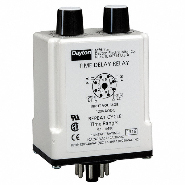
DAYTON Time Delay Relay, 240VAC Coil Volts, 10A Contact ... from static.grainger.com Timing action and terminal wiring. The time relay is a controller whose delay function is realized by an electronic circuit. In the above wiring diagram the io expander and arduino nano are being powered by the first relay board.
In this tutorial we will going to wire the 8 channel relay module driven by our own very owned microcontroller, the below illustration illustrate 8 device on external power source triggered by the relay.
(6) 0.6 (16) wiring diagram direct current sensing current sensing through a current transformer input voltage input voltage sensing circuit a1 b1 11 12 13 14 13 spdt nema 16 14 dpdt nema magnecraft time delay and sensor relays description tdr782 series accessories description the. Control voltage applied to the input terminals (see wiring diagrams below). Double interval relay with control signal. (6) 0.6 (16) wiring diagram direct current sensing current sensing through a current transformer input voltage input voltage sensing circuit a1 b1 11 12 13 14 13 spdt nema 16 14 dpdt nema magnecraft time delay and sensor relays description tdr782 series accessories description the.
Bagikan Artikel ini
Belum ada Komentar untuk "Time Delay Relay Wiring Diagram With Sensor"

Belum ada Komentar untuk "Time Delay Relay Wiring Diagram With Sensor"
Posting Komentar